Zones and Subnets
Zones
Zones solve the problem of overlapping IP address spaces in large or multi-site environments.
Without zones, each IP address must be unique across the entire NetXMS installation.
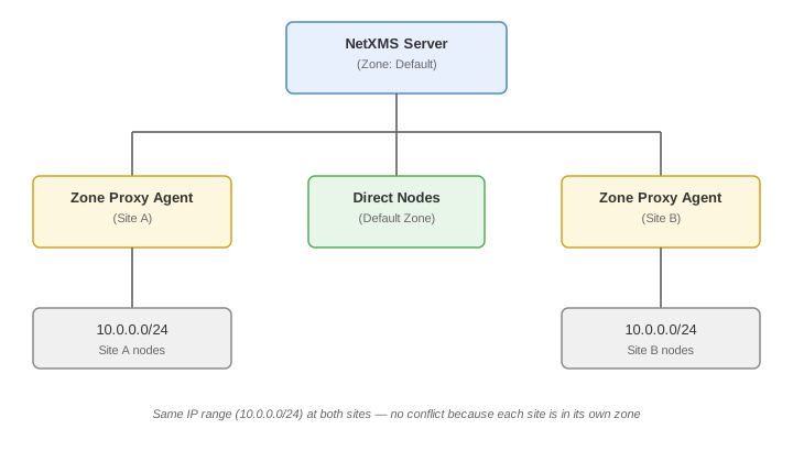
With zones, the same private address range (e.g., 10.0.0.0/8) can exist in multiple locations without conflicts.
Enabling Zones
Zoning support is enabled by default on new installations.
It is controlled by the server configuration variable Objects.EnableZoning (requires server restart to change).
When enabled, the server creates a default zone with UIN 0 and places all subnets into it.
When to Use Zones
Use zones when:
-
Multiple sites use the same private IP ranges (RFC 1918)
-
Network segments are isolated and addresses overlap
-
VPN tunnels connect sites with conflicting address spaces
-
You have a remote site not directly reachable from the server
By default, all objects belong to the built-in Default zone (UIN 0).
Zone Architecture
Each zone represents a group of interconnected IP networks without address overlaps within the zone. The NetXMS server communicates with nodes in remote zones through zone proxy agents — agents deployed inside each zone that relay communication between the server and local nodes.
Creating a Zone
-
In the management client, navigate to the Entire Network root object
-
Right-click and select Create > Zone
-
Enter a descriptive name (e.g., "Site A - London")
-
Optionally enter a zone UIN — if the field is left empty, a unique identification number is generated automatically
Configuring Zone Proxies
A zone that is not directly reachable from the server requires a proxy agent. The proxy agent must be:
-
A node inside the zone with a NetXMS agent installed
-
The agent must be reachable from the NetXMS server (directly or through an agent tunnel)
-
Configured with the required proxy types enabled in its configuration
Enable proxy types in the agent configuration file (nxagentd.conf) depending on the protocols used in the zone:
| Parameter | Description |
|---|---|
|
Agent-to-agent proxy (required for agent communication within the zone) |
|
SNMP query proxy |
|
SNMP trap forwarding |
|
Syslog message forwarding |
|
TCP connection proxy (used for VNC remote control and other TCP-based features) |
|
Web service (HTTP/HTTPS) request proxy |
|
Modbus TCP proxy |
|
EtherNet/IP (CIP) proxy |
|
TFTP file transfer proxy |
All proxy types are disabled by default.
The NetXMS server’s address must be listed in the proxy agent’s MasterServers — proxy requests are rejected otherwise.
For ICMP polls and active discovery scans through the proxy, the PING subagent must be loaded on the proxy agent (SubAgent = ping.nsm).
For the full list of agent configuration parameters, see Agent Configuration.
To assign proxies to a zone:
-
Open the zone properties
-
On the Communications page, add the proxy nodes to the Proxy nodes list
A zone can have multiple proxy nodes. The server balances the load between them automatically (comparing data sender load trend, then data sender load, then data collector load, then CPU load) and assigns each monitored object a primary and a backup proxy, failing over to the backup when the primary becomes unavailable. Nodes in a zone with no proxies configured are contacted directly by the server.
Assigning Nodes to Zones
When creating a node manually, select the target zone in the Zone object selector. For discovered nodes, the zone comes from the discovery context: active discovery address ranges carry a zone setting (honored only when the range is scanned through a proxy — ranges scanned directly by the server are discovered into zone 0), passively discovered nodes inherit the zone of the node whose neighbor tables revealed them, and nodes created from SNMP trap or syslog sources get the zone the message arrived from.
Moving Nodes Between Zones
To move an existing node (or cluster) to another zone, right-click it and select Change zone…, then select the target zone in the dialog. The node is unlinked from its old subnets, its agent connection is reset, and a forced configuration poll is scheduled to rebuild interface and subnet bindings.
Subnets
Subnet objects are automatically created and maintained by the NetXMS server based on interface addresses discovered during configuration polls.
Automatic Subnet Management
When a node’s interface has an IP address with a specific netmask, the server:
-
Calculates the subnet address (e.g.,
192.168.1.100/24produces subnet192.168.1.0/24) -
Creates a subnet object if one does not already exist for that address/mask combination
-
Binds the node to the subnet object
Subnets appear under Entire Network (or under the appropriate zone if zones are configured).
Subnet Properties
| Property | Description |
|---|---|
Name |
Automatically generated as |
IP Address |
Network address of the subnet. |
Subnet Mask |
Network mask (prefix length). |
Zone |
Zone this subnet belongs to. |
When the netmask of an interface is not known, the server derives the subnet using an internally guessed (synthetic) mask; this is not exposed as a subnet property in the UI.
Manual Subnet Management
While subnets are typically auto-managed, you can:
-
Rename a subnet for clarity (e.g., "Server Room LAN" instead of "10.1.1.0/24")
-
Set custom attributes on subnets for use in scripts and filtering
-
Manually create subnets for address ranges not yet discovered
-
Delete auto-created subnets (they will be recreated on next configuration poll if interfaces still reference them)
| Manual changes to subnet objects are preserved across server restarts. However, if the underlying interface data changes (e.g., an interface netmask changes), the server may create new or different subnet objects. |
Entire Network Tree
The Entire Network tree provides a topology-oriented view of your infrastructure:
Entire Network
├── Default
│   ├── 10.0.0.0/8
│   │   ├── core-router
│   │   ├── switch-01          <-- appears in two subnets
│   │   └── server-01
│   ├── 192.168.1.0/24
│   │   ├── switch-01          <-- same node, different interface
│   │   ├── workstation-01
│   │   └── workstation-02
│   └── 172.16.0.0/16
│       └── printer-01
├── Site A (Zone)
│   ├── 10.0.0.0/24
│   │   └── site-a-server
│   └── 10.0.1.0/24
│       └── site-a-switch
└── Site B (Zone)
    └── 10.0.0.0/24
        └── site-b-server
This tree is fully automatic and reflects the real network topology as discovered by the system. Nodes appear under each subnet that matches their interface addresses. Since a node can have multiple interfaces on different subnets, it may appear under multiple subnet objects.